• Ahoy and Welcome to the New SSS Forums!!

    As you can see, we have migrated our old forums to new software. All your old posts, threads, attachments, and messages should be here. If you see anything out of place or have any questions, please scroll to the very bottom of the page and click "Contact Us" and leave a note with as much detail as possible.

    You should be able to login with your old credentials. If you have any issues, try resetting your password before clicking the Contact Us link.

    Cheers
    - Bryan

Getting Ready for SHTP 2021

OK, I'm just going ahead and making the main rudder trim tab. I bought some stainless steel, and my friend Len S. welded the bits together today. Then I glued up materials from Greg Nelson onto the shaft. This shows the little templates I made to hold the pieces in place while Len worked his TIG magic.
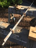
trimtab-shaft-weld1.JPG

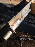
A closeup of the welding. The washer is a "bearing surface". The last 3/4 inch of the s.s. shaft sits in a thin bushing on another piece of stainless at the bottom of the rudder. A couple of nylon washers will separate the foil of the tab, from the bushing area. So thestainless washer takes the very minimal weight of the trim tab. It will butt up next to those nylon washers.

I think this is ridiculous overkill in terms of strength but WTH, right?

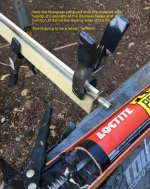
Here, I've attached the lastafoam from Greg to the flat stock welded to the stainless rod. PFL Premium polyurethane glue is doing the work...LOVE this stuff.
trimtab-shaft-weld2.JPG

A bit of a close-up. Note the fiberglass rod I've PL-Premium'ed to the stainless steel shaft. that will form the leading edge of the foil. Once the PL solidifies I'll make some epoxy spooge and get it in there to even things out a big and then longboard sand the lastafoam into the foil shape.
trimtab-shaft-lastafoam-closeup.JPG
 
I've been sanding and shaping the foil. Lastafoam is pretty easy to work with. This is only the second time I've used the stuff.

TrimTab-sanded1.jpeg

The two slabs of lastafoam are glued to the stainless flange, which is welded to the rod. So they don't touch at the trailing edge because they're separated by the thickness of the flange. How to solve that? I mixed up some wood dough/epoxy spooge and mashed it into the space in between the two pieces and clamped the back ends together after I'd done what I estimated to be about half the sanding. The next day, well then there was more sanding, and shaping with a wood rasp.

TrimTab-sanded2.jpeg

The final shape of the foil is awfully "fat" but I don't want one that's more than about 2.25 inches in chord. That will be roughly 15% of the area of the main rudder blade, which is about right. It's half an inch thick....the thickness of the s.s. rod. That's a THICK foil, but what'cha gonna do? The back of the foil, you can see here off to the right. You can't see the leading edge, because of the washer that's welded on. However, remember that I laid on a 3/8 fiberglass rod onto the s.s. rod over to the left. I filled the space between fiberglass rod and s.s. rod with wood dough epoxy spooge and sanded it to pretty smooth. That's now a round leading edge, not elliptical, but hey.....

TrimTab-foil shape.jpeg
 
Last edited:
Here's the layup. There are two layers of 4-inch glass tape laid on with TAP Plastics marine epoxy in medium hardener....my usual go-to. I wrote that it's 8 ounce tape on the picture, I guess it's actually 6 ounce.

TrimTab-glass layup2.jpeg

In some of my other foils I have had to do a LOT of trailing edge cleanup, so this time I clamped it as you see it here. There's wax paper keeping the epoxy from bonding the wood pieces to the trim tab.

It's been kicking off outside for about 6 1/2 hours. I'll take it down right before I go to bed....maybe. It's pretty cold.

EDIT: I don't know why I can't get rid of that "attached image" down below. I've run into this problem, before.
 

Attachments

  • TrimTab-sanded1.jpeg
    TrimTab-sanded1.jpeg
    231.8 KB · Views: 672
Last edited:
Here's a first look at the trimtab geometry. I wish I'd made the tab about 2 inches longer. About an inch of the bottom of the rudder will come off to mount the either steel or oak support there on the bottom. The overall rod length is exactly right, I just need about 2 more inches of foil. Grrr. What's there is rock-solid, though.

trimtab-and-rudder-1.JPG
 
Aaaand, I just won an Ebay auction for a relatively new J-70 assy. So now I'll be taking that beefcake carbon tube i bought from Greg and making a sprit for the Wildcat.

'cause you know, I don't have enough projects!
 
I knew you'd put it to use.

I'll have to make temporary mounts so I can put the pole on deck, somehow and try to suss out where everything should go. I've never actually sailed with an asymmetrical chute before, except for I think two Estuary races with Bob on his J-92 where I just pulled on strings and sort of did what I was told!
 
OK, the credit card is smoking....the 34-pounds-of-buoyancy useless lifejacket is ordered.

Stearns I160 Ocean Mate Adult Life Jacket / PFD

Features:

Designed for Adults Over 90 lbs
Provides a minimum of 34 lbs of buoyancy
Color: International Orange
Includes reflective patches
Heavy-duty hardware with an attached SOLAS whistle
Light storage pocket
Lifting loop
Buddy line
U.S.C.G. Approved Type I Life Jacket
SOLAS Approved with Metal Buckle
Complies with LSA Code 2003 Ed, MSC. 200(80), and MED

552429.jpg

I guess it's not useless. If I actually have to jump in the water because the boat is sinking, I'll probably strip off the inflatable and grab that one.

The new handheld VHF with GPS and DSC is ordered. Wow, the price dropped almost $100 from when I priced them out, about 9 months ago. While my 10+ year old simple Uniden-made West Marine handheld still works fine, it will be nice to have the DSC on the Bay when I get back and I'm sailing the piper, or cruising the delta in a small boat.

New lower lifelines from Ryan and Rogue Rigging are now on the boat. A close reading of the rules says that the depth sounder must be "Permanently mounted", so I'll do a haulout in March and super-carefully ream out the inner glass and balsa core to make a place where I can install the transducer.

The sprit and the assy should pay off during the middle part of the SHTP, and I got that chute for $400 plus tax and shipping...$480. What a steal.

----and the screaming orange eenxy weenxy storm jib is ordered. May it never come out of it's bag.
 
As requested-

I bought the canoe used from a neighbor in 1967. It was light and built with fiberglass cloth. It was not well suited for going over ledges on the Delaware River, so with fiberglass worn through on part of keel, it was mine. The repair was easily completed. At about 50 pounds, the canoe was a keeper.

Being influenced by Adirondack Guideboats, it seems rowing would be a good change.

Luckily, I ended up with a pair of light, 7 foot spoon blade oars and some suggestions for rowing dimensions. The oarlocks needed to be extended from the gunwale and the canoe stiffened.

image.jpeg

The first iteration looked like this.

The gunwales/inwales were needing replacement and the aluminum outriggers were crude - plate aluminum shaped after cardboard patterns were taped together. It was tested at Virginia Lakes at 10,000 foot elevation and seems OK, but a little crude.

image.jpeg

Serious modifications came next. New gunwales / inwales. Seats changed to webbing. Four foot decks on either end, as well as bracing for the hull at the rowing station. I also wanted the decks to have a high ridge at centerline so decks would curve downward. Trimming about 1 1/2 inches of shear helped get nicer deck shape.

The original deck plan was to use plywood, but fastening did not come up with easy solution. Being intrigued with skin-on-frame construction (but with no experience), I Opted for fabric decks.

image.jpeg

Some of the framing and deck supports.

For fishing use, a depth sounder fish finder was added. A small 1 pound lithium ion battery powered it.

image.jpeg

This was getting close to the end, but the rowing was fussy. It turns out the height from seat to oarlocks was 7-inches and most recommendations were 8-12 inches.

One last change is in the works (maybe). The rowing outrigger will raise oarlocks 1 1/2-inches and solve the problem of loosening screws on aluminum outrigger.image.jpeg

The photo also shows bracing from seat support to hull. The fiberglass was very flexible. A strip planked boat with fiberglass would be much stiffer.

Ants
 
Last edited:
It's time to build the brackets on the main rudder, for the trim tab. The stoutest example of this construction that I could find online actually is in bronze, which might be of interest to a few of us...

This incredibly complex document discusses in great detail, the design of a trim tab system...

http://www.svsarana.com/selfsteering gear/sarana trim tab.pdf

If you want even more from them, visit here: http://www.svsarana.com/selfsteering.php

Their blog, if I remember correctly, has photographs of their outrageously strong...and outrageously heavy trim tab system on their double-ender.

Anyway, so I've been back and forth, what to do, what to do about the brackets. Use stainless steel straps, which can be unbolted so the whole thing can come off, or epoxy sturdy oak brackets to the rudder to hold the trim tab? Stainless steel underwater really needs zincs on it to stay in one piece. Stainless is also heavy, and the rudder and trim tab itself are already pretty heavy. In the end, I'm opting for oak and epoxy, with some starboard UHMWP bolted in with stainless at the bottom for a bearing surface and an intermediate bracket near the waterline, also with some UHMWP around the shaft for support. The upper two brackets will also be oak, with the McMaster Carr pillow bearings bolted on. If those disintigrate, I'll replace them with UHMWP.
 
Two things contrbuted to me deciding to 'glass the brackets to the rudder, rather than bolt them. 1.) I could make all the brackets-strut and so on out of $14 worth of 4 inch wide, 1" oak, rather than $30 worth of stainless steel. I'm facing some pushback at home over the SHTP ongoing expense.... and 2.) Alan Steel was closed on Wednesday, when I went over to get the stainless. Instead of getting nowhere all weekend, I opted to make the stuff out of wood and epoxy, UHMWPE and glass fiber.

First up, cutting out and gluing up the upper trim tab rod bracket, and also the strut at the bottom of the rudder that takes the weight of the trim tab.

trimtab-bracket-and-strut.JPG

While I was at it, I trimmed down the tiller for the Piper to the appropriate thickness.
Here's the upper trim tab shaft bracket. It will get a strap of 1" glass tape all round the outside edge. That's probably overkill, but hey. It's a little clunky-looking, I might put it on the saw again and make it a touch more svelte. it will only take side-to-side loads of probably 40-60 pounds, at most.

trim-tab-shaft-bracket-upper.JPG
 
After cutting everything out, smoothing down the epoxy/sawdust spooge with a wood rasp and a bunch of sanding, the bracket tapped nicely into place. Yet more sanding on the rudder will be needed to get a good bonding surface for the glass tape. There's a pillow bearing that goes above the hole that the trim tab shaft goes through. The shaft goes through that bearing, it's pretty low friction.

trim-tab-upper-bracket-in-place.JPG

Here's the lower strut, the piece that actually supports the weight of the trim-tab, which is probably about 10 pounds. It's oak, it will get wrapped in fiberglass. Where the trim tab shaft goes has now been cut back and the last thing I did today was make an UHMWPE "bearing" that goes right there, screwed to the oak with four s.s. wood screws. There's been some water intrusion into the rudder from cracks in the bottom fiberglass, so when I trimmed off the bottom inch, there was some drying-out to do. The doug fir core was fine, just needs a day or two or three to dry out. Three lag bolts attach the strut into the bottom of the rudder, as well as a bunch of fiberglass holding all this in place.

trim-tab-strut-mockup.jpg
 
After much staring and debating...where to put the middle support bracket, I finally opted for a location which might get wet, but will more properly support the trim tab shaft....it's more in the middle. We'll see how the aluminum and bronze pillow bearing does, down there. I'll keep it oiled.

Anyway, the two upper brackets are glassed on, as of today. I sanded off the paint, down to bare glass and used epoxy/sawdust to make a fillet. 1.5-inch tape went over that. The top of the antifouling paint is well above the waterline. The waterline is actually right where the top of the trim tab is. You can still see a hint of the line, in what's left of the antifouling paint on the rudder.

trimtab-rudder-brackets1.JPG

Looks like I got it pretty straight! The red thing is our patio umbrella, fresh out of the spin cycle on the washing machine.

trimtab-rudder-brackets2-end.JPG

Now there's more sanding to do, and then paint. Then I mount the shaft bearings. THEN I slather epoxy all over the endgrain at the bottom of the rudder and take the strut off and wrap it with fiberglass. Once everything kicks off, I crank down on the bolts holding the strut to the bottom of the rudder. It needs to dry out for a few days. Then I make up epoxy and sawdust spooge and shape it....put a layer of 'glass over the whole thing...wait....apply antifouling and call it good.

Oh, I need to do some microballoons/epoxy and sanding to the trailing edge of the trimtab, itself.

trimtab-rudder-brackets3.JPG
 
The new-to-me J-70 asymmetric spinnaker has arrived, so I set up the end of the pole with some wood to distribute the load and an eye bolt. I hoisted the sail in my slip, today,as there was essentially no wind.

Asymmetric1.JPG

I don't know much about assy's, but it seems to me like this is a little bit long on the luff/leech.

Views of the pole...

Asymmetric-pole1.JPG

There's no way to get the outboard end of the pole on the centerline. The bow pulpit won't let it happen.

Asymmetric-pole2.JPG

Pole is about 45% extended, 55% on deck.
 
I'd sure like some comments from folks here who know about asymmetrical spinnakers! That's a J-70 spinnaker.

j_70_drawing.jpg

forestay length is 27.8 feet
J = 7.7 feet

By doing a little math and measuring the pictures on my screen, I come up with a masthead-to-stem distance of 30.8 feet.
The S2 7.9 has a headstay length of 32 feet...so the S2 has a significantly taller hoist than the J-70 by a foot and a bit.

The J-70 has a J of 7.7 feet
The S2 7.9 has a J of 9.5 feet

Add in the extended length of the J-70's pole and that makes the "spinnaker J" of about 12.4 feet.

I'm guessing that the sprit I have on the Wildcat, as set up in the picture is about 16 inches past the stem...1.3 feet. So that makes the "spinnaker J" about 10.8 feet. Now, I have the sprit set up on that jury rig with the 2 x 4's. The permanent setup will pretty surely give me at least another 6 inches, maybe 8 inches of extension. So my "actual" working spinnaker J will be about 11.5 feet.

That's a 10 inch difference in J-length

So the S2 will have a shorter "spinnaker J", 11.5 feet vs. 12.4 feet ...about 10 inches shorter
but a slightly longer hoist 32 feet vs. 30.8 feet than the J-70.

Wind was VERY light in the marina when I set up the spinnaker for that shot...just barely enough to fill the chute. It was trimmed to a point pretty far back in the boat, probably close to where a J-70 trimming point would be. It was trimmed in to somewhere between close reaching and broad reaching for the picture.

So....dock talk at the marina was that the leech was tighter than the luff, and admittedly, when I pulled the leech down about a foot, the sail seemed to look better. However, I was doing the pulling, which didn't give me a very good view of the sail. QUESTION.

Does this sail need a recut to make the luff a bit shorter?
 
Last edited:
You asked, so three comments:

A couple times I forgot to extend Ragtime!'s 5.5' sprit and the kite still flew okay, so exact measurements, angles etc. aren't essential. That said . . .

Most asymms work fine on a reach but to go downwind you need as much separation as possible between the main and spinnaker = a longer sprit. This can be expensive on your rating. I'd temporarily rig up a "sprit" so you can try it at different extensions. Maybe borrow a long spinnaker pole instead and strap it down on the foredeck, but so you can move it. Go sailing and see how much extension you'll need to keep the spinny full at 130 AWA in light-moderate wind and 140-150 in heavier air. Then see what that JSP will do to your boat's rating. This will cost some money, either for Jim Antrim to run the numbers or for a test submittal. (I think if you're a YRA member, rating changes are free.)

Based on the photo above, I would not shorten the luff - it looks good. In fact, to go downwind I estimate you'd need to ease the tack line at least 12-18" from where you have it tied to the sprit (the tack line needs to go through a block and back to the cockpit.) The long luff, when rotated to windward by easing the tack line and sheet, is what enables you to sail deeper downwind. Some early A2's would even drag in the water because their luffs were so long. Then the trend went to a boxier shape with rounder shoulders - remember that photo of Ragtime! with her newest A2, going into Half Moon Bay?
.
 
Last edited:
Untitled 2.jpg

by doing a little measuring and math I come up with a "hounds to sprit" length of about 33 feet. for my S2 7.9.
Doing some measuring and calculations for the J-70 with the sprit extended also comes up with a "hounds to sprit" length of about 33 feet.

This has got to be awfully close.
 
You asked, so three comments:

A couple times I forgot to extend Ragtime!'s 5.5' sprit and the kite still flew okay, so exact measurements, angles etc. aren't essential. That said . . .

Most asymms work fine on a reach but to go downwind you need as much separation as possible between the main and spinnaker = a longer sprit. This can be expensive on your rating. I'd temporarily rig up a "sprit" so you can try it at different extensions. Maybe borrow a long spinnaker pole instead and strap it down on the foredeck, but so you can move it. Go sailing and see how much extension you'll need to keep the spinny full at 130 AWA in light-moderate wind and 140-150 in heavier air. Then see what that JSP will do to your boat's rating. This will cost some money, either for Jim A. to run the numbers or for a test submittal. (I think if you're a YRA member, rating changes are free.)

Based on the photo above, I would not shorten the luff - it looks good. The long luff, when rotated to windward by easing the sheet, is what enables you to sail deeper downwind. Some early A2's would drag in the water because their luffs were so long. Then the trend went to a boxier shape with rounder shoulders.

Thanks, Bob!

My gut feeling was that this was pretty close, which is why I bought it. Good to know that a few inches here and there will not make a heee-uge difference. I have the carbon pole...that's what I have, so I'm limited by that. Since the pole is only 5' 9", sticking with the 55%/45% ratio, that gives me at most, 31 inches of extension past whatever bracing point I can rig up. Maybe I can get 2 feet out past the forestay? Hardly very racy.

I bought this for one reason....Days 5-10 of the SHTP. Well, that and the fact that Greg parted with the pole for a ridiculously bargain price, I've never actually played with an asym before, and I'm up for learning about something new.

OK, no cutting down of spinnakers without more testing! THANK YOU.
 
Back
Top