• Ahoy and Welcome to the New SSS Forums!!

    As you can see, we have migrated our old forums to new software. All your old posts, threads, attachments, and messages should be here. If you see anything out of place or have any questions, please scroll to the very bottom of the page and click "Contact Us" and leave a note with as much detail as possible.

    You should be able to login with your old credentials. If you have any issues, try resetting your password before clicking the Contact Us link.

    Cheers
    - Bryan

Getting Ready for SHTP 2021

I just snagged one of these...https://www.ebay.com/itm/Seco-Larm-...DoAAOSwrPZcvsm5:sc:USPSFirstClass!94025!US!-1
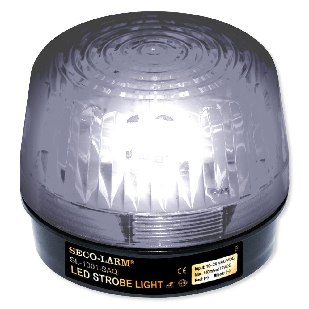
SESL1301BAQx_media-Clear-570.jpg


Greg Nelson pointed out something very much like this many years ago and I've had them on both my Santana 3030 and on the Santa Cruz 27. Seal the lens threads with silicon and they're waterproof.
 
Today I'm just fairing the pendulum oar blade, with 95% of the fairing effort spent below the waterline. I also grabbed a couple of little s.s. bolts and locknuts from the hardware store when I went in for some plumbing pieces, and now the wind vane blade is attached to the carrier. That will be worth a photograph, once I get the counterweight on.

Oh, and maybe some painting, today. Work is slow.
 
Here's a first look at the Vane assembly, actually on the pole.
VaneAssembly-firstlook.jpg

It's by no means completed, but it's far enough along to get an actual look at how it will appear on the boat, so I clamped it to my sawhorse and snapped that shot.
 
I see that my thread title has been changed to 2021! LOL.... I'll be having that talk with Joan this week!
 
OK, after doing nothing yesterday, and not much on Friday, I had two hours to get some stuff done today. I measured, and put the pendulum oar on the table saw, and cut the balance cut-back today. I actually probably should have cut back another 1/4 inch, but we'll see how this works. I also glassed the raw, front edge, and smeared epoxy on the now-bare, trimmed-off top edge to seal it.

pendulumOarCutback1.jpg

I trimmed the bottom and got some glass on it. I'm somewhat concerned that the foil is not as symmetrical as I thought it was. This could mess up everything.

foilview.jpg
 
When I set up the windvane mast and the vane assembly the other day, I left it up for about 8 hours, clamped to one of my sawhorses. Come to find out that the weight of the wind blade, the carrier, and the counterweight was too much for the single-screw and lockwasher that I had used to attach it to the little aluminum "triangle" that I made. I needed something stronger. ...something that wouldn't "sag" and change the angle of the pivot rod.

So I measured stuff and eyeballed carefully, and marked up a piece of aluminum stock that I've had forever. Then, since I haven't gotten the workbench cleaned off yet, I' clamped it to the fence and hacksawed out this piece.

It's rock solid, and will NOT move from the 20 degrees I designed it at!

carrier-ver2-1.jpg

carrier-ver2-2.jpg

WIN!
 
I puttered for about 4 hours but just did little stuff today...JB-welded an aluminum gusset onto the crosspiece that carries the cables. Once that's set up and back on the vane, it should make the push-pull of the cables more solid...less slop. I drilled that crosspiece as well...

wire brushed, primed and painted the counterweight.

PL-Premium'ed wood blocks on the pendulum oar carrier to screw the gudgeons into. We are getting close to painting-time for the oar carrier. Nothing here is worth taking a picture of!

I also knocked a wedge into my emergency rudder cassette, as when the wood dried, it shrank and the plywood sides bowed in a bit. It was impossible to get the rudder more than halfway into it! I'll leave this wedge in there for a week, then take it out and knock it into the other end. That should open things up. I also epoxied the bushings into the gudgeons; a two-minute job that took me three months to do!
 
Today was a low motivation day. I painted some bits...stared at the dinghy pintles and decided that I blew it, I made the the rudder too thick for them, so I need to either buy new ones or make some, and hacksawed the corners off of some other bits.
 
Yesterday I had a motivational crisis LOL...so between yesterday and the day before all I did was:

1. prime, then paint the oar carrier
2. dip the counterweight in a can of marine enamel to get it really thickly coated.
3. Hacksaw, and round some of the aluminum bits that the hinge on top of the oar will ride on
4. epoxied the vane carrier assembly to the tube that goes around the mast.
5. put the piece of redwood that the cable ends will go on, on the belt sander and true'd up some angles, got rid of some saw gouges.

Today, so far I blew up the budget at the bike shop on ten feet of teflon-lined cable housing, ferrules, and stainless steel brake cable. This was something like 30 bucks.

no pictures....this is not terribly photogenic stuff.

I measured the thickness of the pendulum oar and it's 7/8 th's of an inch thick. My free pintles are for a 3/4 inch rudder. I can cram it on there, but I can't shove it all the way on without cutting through the glass and carbon. With it 80% of the way on, the pin is way out in front of the leading edge, and while I can get both of the through-bolts on them, the axis of rotation is going to be pushed forward...what I DON'T want. So today I bought two 1/4 inch bolts, and I will cut the threads off and bury them in redwood and fiberglass, to make DIY pintles which sit very close to the leading edge of the pendulum oar cutback. THAT is photograph worthy!
 
This lousy picture shows the triangular gusset I made to support and increase leverage on the aluminum piece to which the linkage cables are attached. The triangular piece is edge-glued to the main carrier with JB Weld and then I slapped on a couple of gussets to reinforce the attachment, also with JB Weld. It's somewhat less than glamorous, but it will work. I use JB Weld a lot when I'm working with metal, as I don't have welding or silver-soldering/propane brazing capabilities....though I probably should get the relatively inexpensive kit to be able to silver-solder/braze aluminum.

gussets.JPG

BLARG!!!!... @#$%^&*()_!!! ... the gudgeons are bigger than 1/4 inch. OK, so they'll have, what we'll call..."bushings" made out of PL Premium. Yesterday I put some redwood on the table saw and VERY carefully, using pusher sticks to keep my fingers away, cut small angled pieces to hold the bolts. I used my Dremel-clone rotary tool to grind grooves in it. Then I hacksawed the threads off of two 1/4 inch stainless steel bolts. I put them on my grinder and rounded off the bottoms, then filed 'em smooth at the bottom. One is about 1/4 inch longer than the other. I scratched up the top inch of the bolt with a hacksaw and then used JB Weld steel-reinforced epoxy to lay them into the grooves I cut in the wood.

pintles1.JPG


The wood will be epoxied to the leading edge of the rudder, in the cutback area, and then attached with 3-4 straps of 1.25-inch wide glass cloth in epoxy. I wish I had some linear carbon fiber left, but 'glass will be strong enough for this.
 
Today was a fun day. After some paint and sanding...drilling out the "bushings" I have in the oar carrier gudgeons, I screwed the gudgeons to the oar carrier and...wow....put the pieces together.oar-carrier-assembly1.jpg

That's a 6-foot tall garden ladder, except that it's more like about 5' 10". The pendulum oar is about 2 inches off the ground. It's got two coats of gloss exterior latex on it. Anything above the waterline on the pendulum oar is hella strong and also hella UGLY. If it all works, I might hit the upper half of the oar with paint stripper, then add a fairing compound to prettify it. Or not.

Right now the oar is a little tight, but I'll waggle it back and forth a whole lot over the next couple of weeks and see if it eases up.

I also made these two little thingamabobs, the function of which you'll just have to wait and see!

stopper-donuts1.jpg

stopper-donuts2.jpg
 
In which we discover what the deal is with those donuts.

Today I took a deep breath and epoxied/tabbed a mess of stuff onto the fiberglass tube that I made. I bent some aluminum bits, drilled them, and threaded on the bicycle brake cable housing stops. Then I eyeballed like crazy, drilled some holes and voila, they're ON the wood block that is supposed to hold them....and pretty darned well, too. When I look through the holes in the cable stops I see the bolts/nuts where the cable will terminate. With some work with the round wood rasp and sandpaper, one of yesterdays donuts was made ready..

Everything is now aligned, epoxied and tabbed to the fiberglass tube.

carrierblock-epoxied.jpg

cablestop-epoxied.jpg

...and here's one of those donuts, from yesterday...

cablestop-endplate-epoxied.jpg
 
Aaaaand, the purpose of the donuts is revealed. The windvane part of the system is Done...except for some paint! All the bits and bobs are made and glued/screwed in place. I am stoked!

windvane-done1.JPG

windvane-done2.JPG

How to set the course? At the top of the green "mast" is fiberglassed one of those wood doughuts. At the bottom of the fiberglass tube that I made to fit around the "mast" is another one of the wood doughnuts. The weight of the whole assembly rests on those two doughnuts. The entire thing rotates around the mast.

How to lock the thing down, on course? Easy.

2491280master.jpg

..and actually, if that doesn't work, I have a second option...
 
I am getting close! I went to Alan Steel in San Carlos yesterday to get some aluminum bits, but they were closed, I assume because of COVD-19. OK, so I'm saving money by making what I need out of wood, fiberglass, epoxy and PL Premium polyurethane.

Pendulum Oar tiller arms.

TillerArms.jpg

The linkage "bicycle brake" cable housings have to terminate on the oar carrier somewhere, but I realized yesterday that I can't just screw some aluminum bits to the main oar carrier shaft, the angle will be wrong, which will add friction. So I inset these blocks about 1/8th of an inch into the arms and glued 'em down with a generous quantity of PL Premium. they'll get painted to match, probably tomorrow.

CableStops.jpg
 
Last edited:
It seems it is getting close to the"Aha" moment for me, when the water and wind sections are connected in proximity. I am patient and can easily wait ............

All things will be obvious - eventually.

Ants
 
A little bit of paint, a little more fiberglass...some drilling, some aluminum bending, and all the last bits are on, to test in real wind to see if the wind vane will turn the oar. Maybe tomorrow, and for sure on Sunday, down at the Port of RWC, I'll clamp everything to a ladder, attach the cables, and we shall see!
 

FAIL

There was a pretty good breeze in the front yard today so I set up the entire shebang, to try it out. In the video, the cables have been disconnected, and you can see that the windvane moves very well in response to maybe 5-8 knots of breeze that wafts in from various directions. I greased the gudgeons and pintles of the pendulum oar, and it's very smooth now. But when I hooked up the bicycle cables and housing....nothing moved. A few tweaks on the pendulum oar, moving it from side to side revealed that...sadly...there's a huge amount of friction in the system. It's really stiff, way, way too stiff to work.

Now, that might be improved by using less cable and housing, and a straighter "run" to the pendulum oar, but when I have this actually on the boat, I'm going to need about as much cable and housing as I have pictured, here.

SO this is a great big flop....a $40 flop, I might add, *ouch*! though Jan Alkema linked up his with steel cable, so maybe I can use the cable, at least. If not, 12 feet of 1/8th inch dyneema is about four bucks, so I'll use that.

Hmph! Well, I've been harboring this idea for ten, twelve years, it's about time I tested it out.
 
Chuck Warren just donated Antipodiste to the RYC Foundation. Pretty sure it has a Navik on the stern...
 
Back
Top